• Folks, if you've recently upgraded or renewed your annual club membership but it's still not active, please reach out to the BOD or a moderator. The PayPal system has a slight bug which it doesn't allow it to activate the account on it's own.

68 CREE LED 3 mean well 60-48p driver parallel build

fatoldsun

NJRC Member
Finally getting my build underway – I have all my LEDs wired – I just need to figure out the mean well side of things… Plan is to run 3 sets of parallel strings as follows (plan includes: 1.0 OHM 1% 5W resistors that I will use for each string along with 1A fast blow fuses to protect things with the parallel setup)
12x2 royal blues
10x2 colors (4 blue, 2 green, 2 red, 2 UV)
10x2 mixed whites (4 natural, 6 cool)
2x2 moon lights (series but split between both heatsinks)

Baby steps – the first few royal blues going on the “right side”
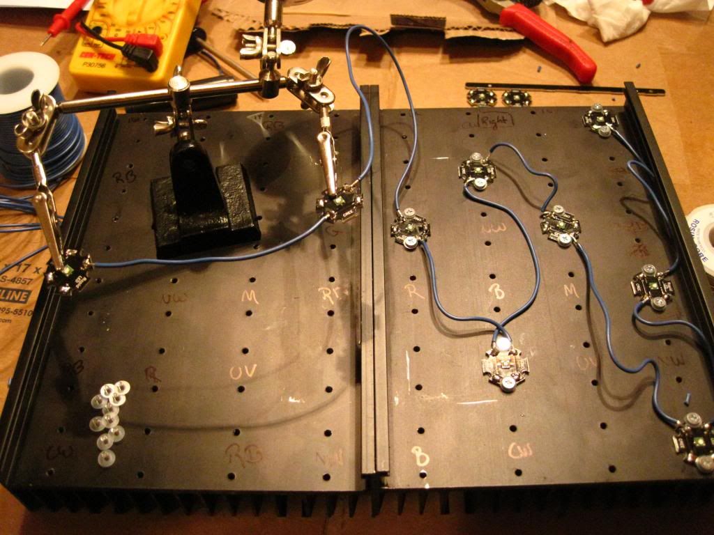
IMG_2034_zps72de7cad.jpg

Adding the other colors:
IMG_2036_zpsc1252d7b.jpg

Progress, working through the whites….
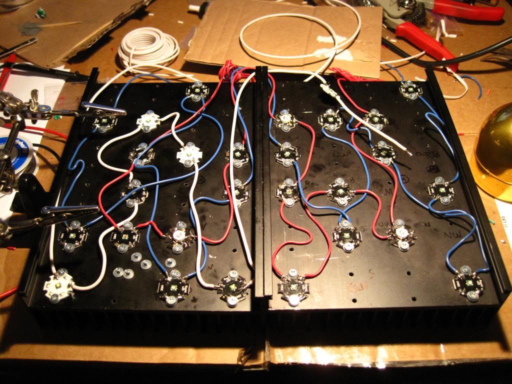
IMG_2038_zpsdb588187.jpg

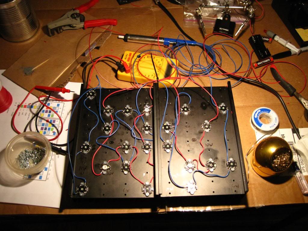
LEDs are all wired/ soldered and tested for good solder joints and shorts, etc…
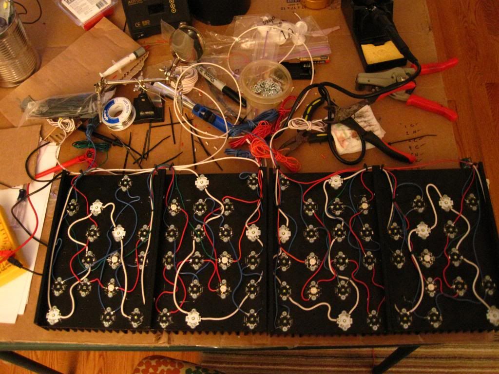
IMG_2039_zpseb93cc1f.jpg


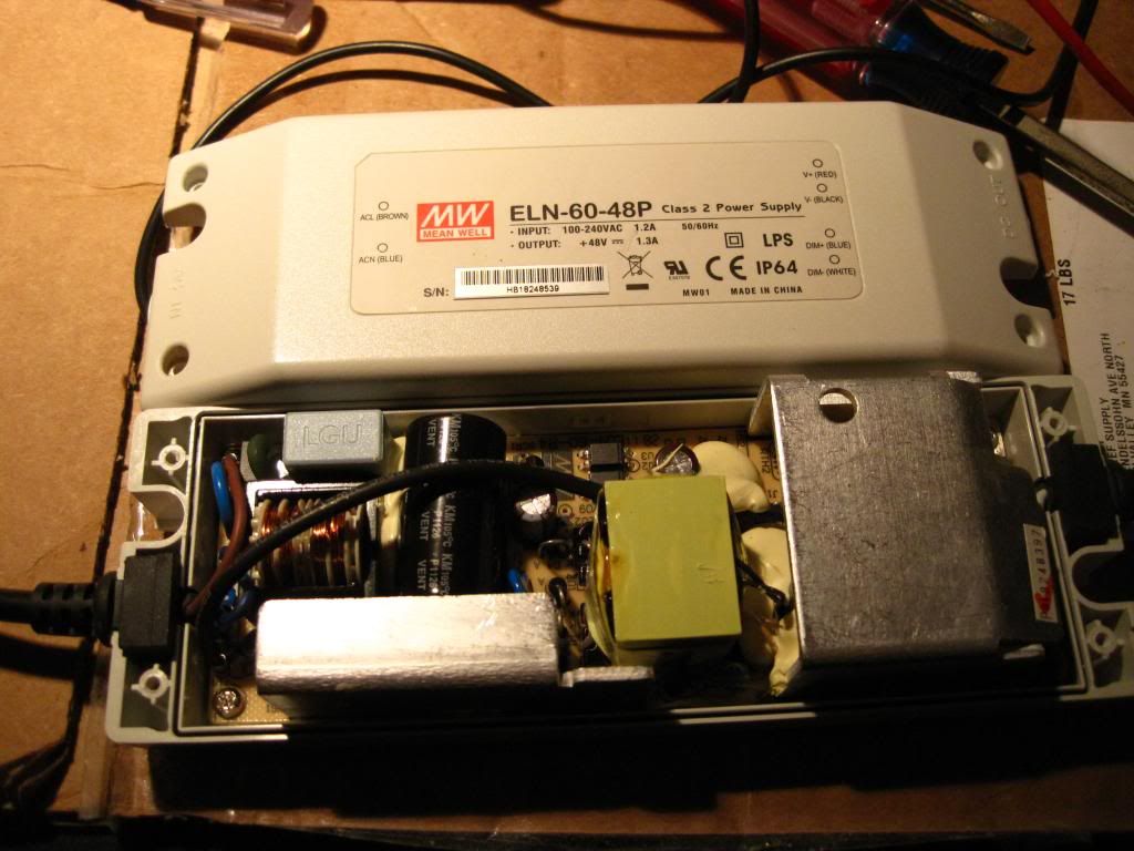
I have 3 mean well ELN 60-48Ps.
IMG_2042_zpsc391cd89.jpg

I’m ready to set up my drivers and I’m a little unsure of the setup with those. I want to adjust the mean well’s outputs to safely operate the LEDs. At first look there appears to be two internal pots – a smaller pot under a metal shield and a slightly larger white pot in the upper right hand corner. Questions are what should I be looking for on my multi-tester?
You can see both here
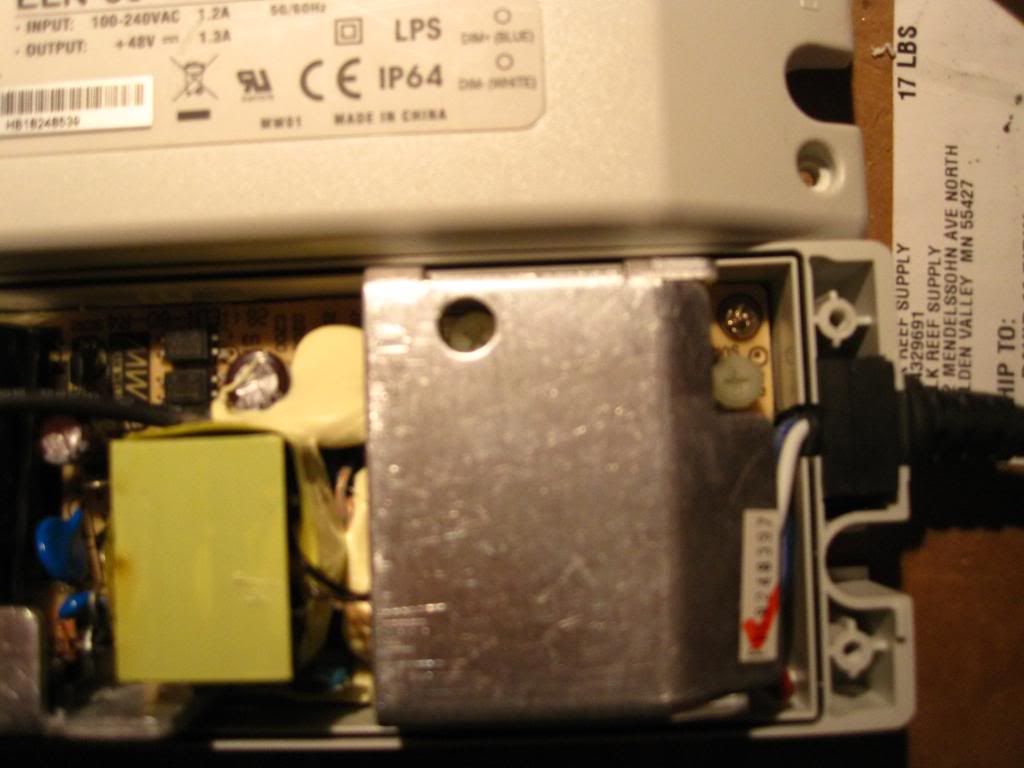
IMG_2043_zps9f0f8bcf.jpg

Here’s my cheap multi tester – it’s served me well for the better part of 15 years
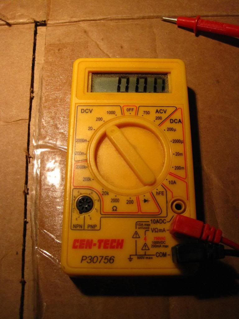
IMG_2041_zps075568be.jpg


Anyone have any experience with setting up a mean well?
I’ll take any input I can get…

…and Happy New Year!!
 
I have to check my notes but im more familiar with the dimmable driver ELN D. I just recently refinish my led and went with solderless led which was super easy and fast to set up. I'll get back to you to see if I can help.
 

fatoldsun

NJRC Member
I think I forgot about Ohm's Law and tried to measure current directly off the driver. I think the law is current = amps or volts \ resistance. Well without the driver pushing voltage through the stars resistance would be =1 so the current would be unchanged from the amperage/ voltage since 17/1=17. Duh. I'll try to hook everything up tonight for at least one pair of parallel strings. Wish me luck
 

fatoldsun

NJRC Member
I set up a single driver to test parallel strings. First test was the royal blues. Went swimmingly. Then on to the mixed colors. Not as well. The "right" string/fixture was spot on. Left not so good. It fired for 3-5 seconds and then went dim. I tried a few times. Right string great, left - dim. I powered off PVM and proceeded to look for issues. Here's where it gets strange. While testing for shorts or other problems i started at 10 and worked back) the second to last light (red, # 9) appeared to have a short. I checked the next on the string (UV, #8) and while short testing it it lit up red. Weird. I moved on and got to blue #4 it lit the whole string (just the multi tester). Now I unhooked from the driver and everything tested fine. No shorts, etc... I'm perplexed!!??!!
I've been sick all week - maybe the NyQuil is finally getting to me
 

fatoldsun

NJRC Member
I'm really confused and feeling a little lost - I went through the entire fixture, one star at a time doing a diode test as described in detail on an RC thread. It showed all my solder joints were ok. I then did the “short” test. Again, as described on that thread - the difference was I used the diode setting instead of testing for resistance (as one poster suggested) In all of the stars, I found one short. I had a few stars that I bought from other builds and one (a blue) was a little messy. I did my best to clean off all of the old solder but I missed a small line that stretched from the pad to the raw edge of the star itself, which in turn caused the short. I found this going from pad to screw and found that the screw was grounding the circuit. I removed the star, inspected it to find the issue. Cleaned it up and resoldered the joint. I re-tested it about 9 different ways (both the screws, scratching a small spot on the sink to make a clean contact and all around the edge of the star. Everything looked good. Then I retested the entire fixture for a short just to be safe. As you said, it only took a few minutes and I was not in a rush. I was trying to be extra cautious (especially after finding the one short) so now I am surprised. Now I am at a loss as to where to look. Admittedly, the pads come VERY close to the screws in some cases, but I used nylon washers on every screw and thought that would cover me where a screw head may sit on top of some spill over on a pad. Now, like I said, I’m at a total loss as to what to do next. I’d prefer not to redo the whole string. I guess I may have to if I still can’t come up with anything else. I will retest every which way again tonight.
Does anyone think the result I described sounds like a short? – with the lights firing and them running dim. Could it be an issue with the resister, fuse or PVM? If it did short, am I on a mission to find a bad star? Could that be why it’s lighting dim and passing current from the multi-tester while still tied to the resistors? (it’s not a capacitor, I didn’t think resistors stored power the way caps can). After I powered the light down, it flashed on once. Also, I tested across the resistors after checking the royal blue strings. I then used the same set up for the mixed color string – the RBs also flashed – is it possible I damaged the resister, fuse or PVM doing that? IS there something I can test on that side of the equation after retesting all of the stars but before I fire it up again?

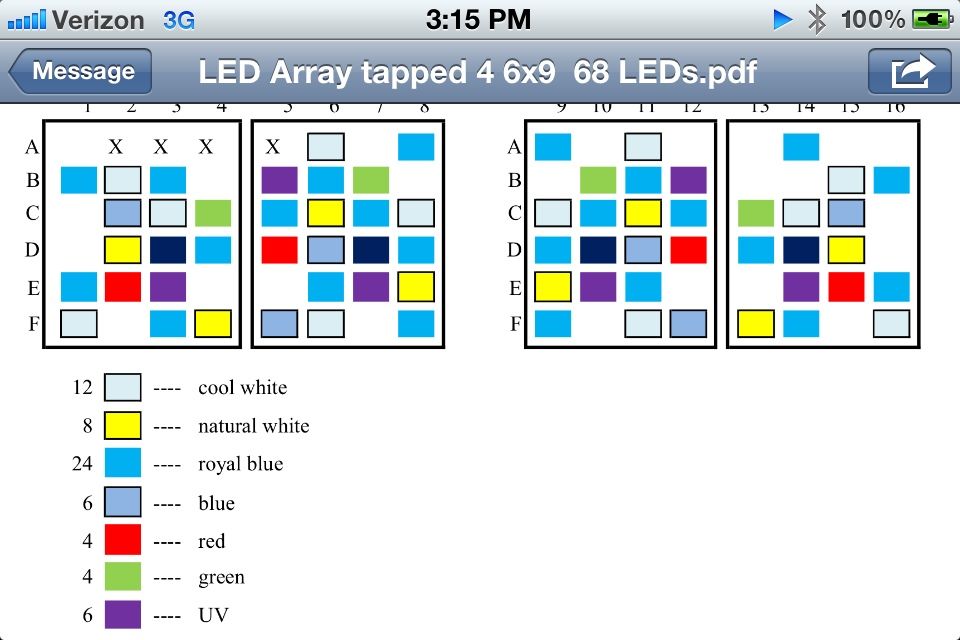
here's the layout I went with I wanted to set the two modules up as mirror images so I could keep it organized with multiple strings...

1D37534E-0D65-4C0D-ADEC-E7F82BCD586E-7023-00000C2C9D39A140.jpg


Thanks for the input guys. I’m really anxious to get this up over the tank. My halides are effectively expired and my coral is suffering without good light. I’m hoping to get something up before I lose the whole tank. At this point my SPS is about 80% STN’d
 
Did you do any adjustments to the internal pots? i saw that you posted the picture asking about the both of them, If you are running parallel strings and have not adjusted the pot (the larger one outside the metal box) down to roughly 700-750mA then that could be over driving the leds and they could be adversely reacting to the higher levels that the meanwells produce from factory settings, which are close to 1300mA if i recall correctly. If you can, try adjusting that and monitoring the levels down to where they should be, hopefully that helps. If not I as clueless as you are lol
 

fatoldsun

NJRC Member
Thanks for all the guidance. I found a UV star that was behaving oddly. Still tested ok but I got inconsistent results testing from the pad itself. It tested fine from the wire off the next led which was weird but I was looking for anything so I redid that star and both wires leading to it. I also avoided the pad since the led seemed to be lose on the star I re-soldered it to the star and used that as a substitute for the pad.


So now onto my next step, where I'm really lost is how to set up the drivers.
1. What setting do I want to test across the resistors to get my string mA?
2. Should I use the internal pot to adjust or the PVM controller?
3. How do I test individual for balancing? - how important is balancing if things look ok?
4. Drivers - I have 4 drivers so if I do 3 sets parallel (1 pair royal blue, 1 pair mixed colors, 1 pair mixed whites) ill have an extra driver - or should I run the whites on their own drivers and only parallel the colors? In other words, 3 or 4 drivers. I'd prefer 3 for space savings but not at the expense of coral growth/health. I think with a 90g display and 64 LEDs I will probably have to dim the fixture. Any thoughts?
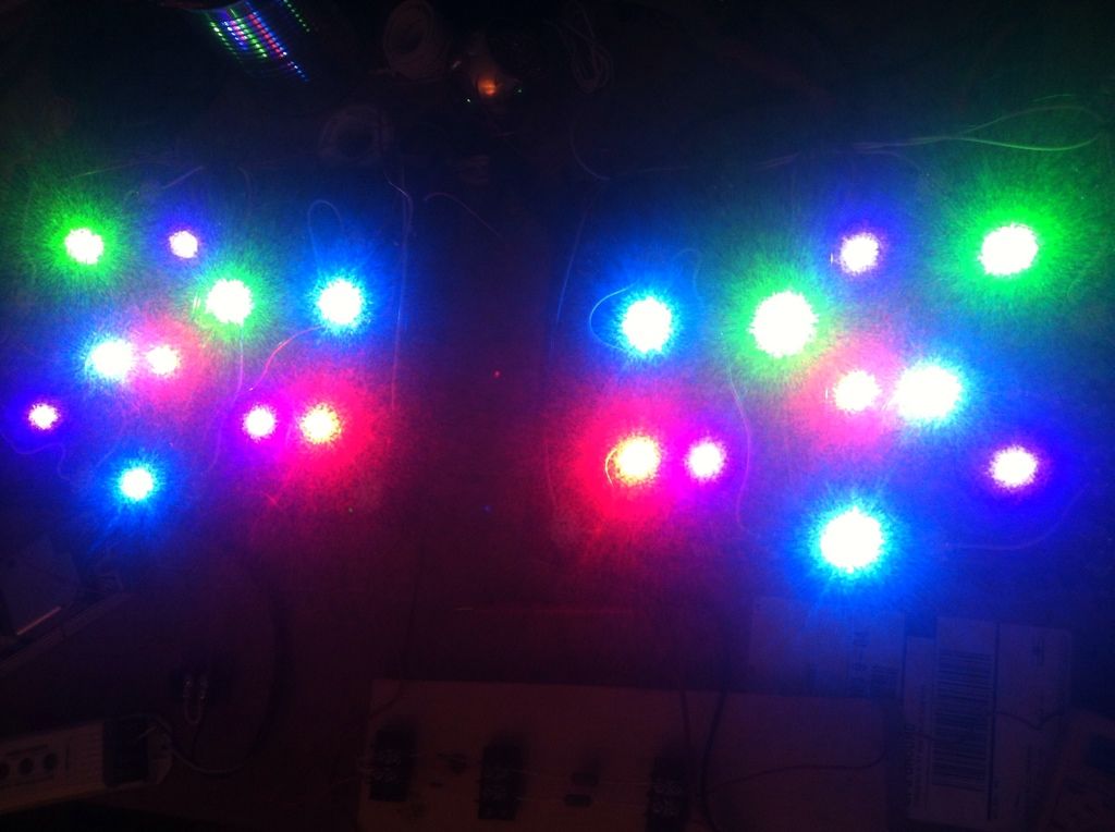
Here are shots of the strings. my phone's camera struggled here and these are with the interal pot at about 20%...
Mixed colors:
57A9736D-74D2-4335-90ED-615A79AD190E-918-000001496FE1270C.jpg


Royal blues:
D6B111A3-EFCD-44EF-AB58-392270590EFC-918-000001497874DA42.jpg


Whites:
7CFD2B83-9F5F-487E-8107-CB86E7782F8A-918-0000014975AE7399.jpg
 

fatoldsun

NJRC Member
I think I'll be testing /setting up the drivers tonight. I think I might need to wear a welding helmet for the task of balancing the strings. They are really bright. Kind of like staring at a camera flash…

Next steps:

*I need to come up with a way to house the terminal blocks, and fuses/resistors, etc... I’m using with the parallel strings. I was thinking of using Delphi type plugs that are used for car harnesses (like these) so I can easily unplug the individual modules if I need to service something and can do so without pulling the whole canopy/hood off to do it.

Choice A:
…would be to use a double gang outdoor outlet boxes with a sealed cover. With the resistors I got I’m hopeful that resistor heat won’t be an issue. The driver for each will be mounted to the lid for the set it’s running. Keeps the electronics off the wood and provides some protection from the evaporating saltwater. I have to have a relatively contained system – I have a stand under the tank to work with and it has a lot of equipment crammed under there. I’d rather keep the drivers and PWM (I wish I knew why my phone KEEPS auto-correcting to PVM!! – then again I don’t know why it changed my title to “meal well” I can’t blame it for the “06-48” vs. “60-48” – that was a typo) out of the stand:
Choice B:
I have tons of extra wire so I could do a remote control panel – I just would need something that my wife could live with in terms of appearance if it’s not under the stand…. So like a small electrical panel like what’s used for a home security system controller. I found a PWM with a remote so I have flexibility with where I mount that…

**I have to set up the fans although I think I went overkill with 4 fans but I guess it can’t be too cool.

***I need something to mount the lights on/in. I started a hood that was part aluminum frame, part removable wood panels but my drill press went kaput and I need that for the aluminum frame part. I’m going for lightweight if possible. I have the drill working again but I didn’t want to abandon the light itself so the hood was put on hold. I figured I could always set up a temp frame to mount the light just to have it running while I finish the hood.

**** I've collected a bunch of different lenses. I'll need to decide what is getting a lens and get them hot-glued in place.
 

fatoldsun

NJRC Member
I sort of feel like I'm talking to myself, but hey, what the hell, the build continues. I found a perfect “box” - a metal enclosure such as what is used to house the “brain” of a home security system so it looks like I’m settled on “choice B”. Thank you eBay. I did a search and someone in NY had one – 16”x16”x3” (old, but NIB) for $15 with 3 hours left and no bidders. Yay. I had gone to Grainger, Harbor Freight and HD at lunch and the only one that had anything was Grainger – yep for $150 I could get a smaller NEMA 1 box - $50 upgrade for knockouts - so $15 looked like quite a bargain. Now I wanted to make a harness and I found a great source for the Delphi style connectors. If anyone wants to try this, PM me for the website. They were FAR cheaper than anywhere else I found. Like the 6-way male weather-pack was ~$0.70. I think for all of the pieces a 6 way (male, female packs, 12 pins and weather plugs) was < $4.00. Of course I ended up get tons of extra because I love gadgets and weird things like neat homemade harnesses excite me (sadly) so I’ll be waiting until I can make the harnesses to set up the drivers (and balance the stars if necessary). Hopefully this weekend I can get the frame made for the hood and set up the light mounts. The plan is to have the two modules hinged so I can independently raise them if I need access to the tank – one side will stay down lighting the tank (and one will shine in my face, basically blinding me – I never said it was a perfect plan. The only way to avoid that would be to run 6 drivers so I could independently shut off one side. I’ll have to pick up some welder’s goggles – back to harbor freight….)

I’ll post more pics as I progress along
 
this build is turning into awesomeness. I would have gone the same route & DIYed my lights, but I'm challenged in all things electrical :( love the remote control box idea!
 
I'm following along. Cause I'm considering building a DIY for my frag tank.
How many LEDs will I need for a 40breeder?
We're did u order your LEDs , drivers and etc needed for the build?
 
I have been paying attention and getting frustrated just reading and trying to figure out what you are saying. So I can only imagine how frustrated you have gotten. The one thing I am not great at is electrical. Well that and reading a tape measure. I SUCK at reading tape measures. I don't do it enough to be good at it.
 

fatoldsun

NJRC Member
this build is turning into awesomeness. I would have gone the same route & DIYed my lights, but I'm challenged in all things electrical :( love the remote control box idea!

Thanks Ryan!

I'm following along. Cause I'm considering building a DIY for my frag tank.
How many LEDs will I need for a 40breeder?
We're did u order your LEDs , drivers and etc needed for the build?


I’m not sure how many you’d need - there are a ton of formulas floating around – I think the one I see most is based on surface area – so, in inches, L”xW”/16 for SPS = for me that would have been 54 (4 of my “68” are moon so they don’t count) so I’m 10 over but it was really more about my mix of color – there was no good way to get the ratio and spread I wanted at only 54. I figure I’ll probably keep them under 80% power and if I upgrade my tank I may be able to crank it up and use it at least until I get around to a new build.
As for cost and source – I bought stuff over about a year. More than half of it was used 9or abandoned builds) – if you’re patient there’s an amazing number of people who buy all of the stuff and do the research on how to do it after – then they get scared and sell for a fraction of what they paid. There’s also a couple vendors outside the hobby for some of the more universal stuff (like drivers) which can be found cheaper online. You just have to watch because getting stuff from multiple places can drive total cost of due to shipping. When I’m done I’ll post my cost breakdown but I can say I have a lot of extra stuff so if I have enough I’ll make a light for my fuge – otherwise that makes my build more expensive since I still paid for it even if I didn’t use it. And used stuff is hit or miss. I may continue to collect things for other builds but I will stick with abandoned builds and extras and avoid used. Trying to clean solder of a star from someone’s sloppy job is a waste of time and lead to all of the frustration I ran into so far. Final point, get a GOOD solder iron, not one of the cheap Radio Shack ones. It adds to the build cost but worth it. I have a few pages of notes with all the details – everything from what gauge wire and where to get it to what they’re talking about when you read about different “bins” of LEDs. PM me if you’d like to see them. Not sure I’m allowed to post that stuff here without editing a lot out

I have been paying attention and getting frustrated just reading and trying to figure out what you are saying. So I can only imagine how frustrated you have gotten. The one thing I am not great at is electrical. Well that and reading a tape measure. I SUCK at reading tape measures. I don't do it enough to be good at it.

Don’t get frustrated or talk yourself out of it - it’s really not bad at all. Just takes some practice and patience. Then again, for me it’s just like a big puzzle. If my wife wouldn’t make fun of me (and hell, my kids too, and they’re 5) I’d still be playing with my erector set (and legos). This just comes off as more adult. Anyway, you're close to me and I have the solder iron and a lot of the basic stuff that you wouldn't want to buy for "one time" so if you want to give it a shot let me know :)
 

fatoldsun

NJRC Member
Does anyone have an opinion as to use of the spray LED sealants? I've read lots of mixed reviews. I'm less concerned about minor PAR loss and heat transfer efficiency and more concerned with corrosion.

I have an anodized heat sink but it's pre-drilled and there is exposed aluminum in any unused spot. Generally the drill/tap occurs after it's anodized. I'll also be using a splash shield but even without direct contact from saltwater I'm concerned about corrosion. It only takes a millimeter of raw exposed wire between wire insulation and pre tinned stripped wire to start corroding. I'm always amazed at how quickly stuff on the boat corrodes like wires from a VHF radio in a cabin or under a dash - that have NEVER seen direct contact with saltwater.

I'm sure if I had a lot more soldering experience my risk of over exposing the raw wire would be reduced but I'm NO expert and can't compete with a robot or CNC machine that would be used if this were a factory build. Also I don't have a sealed housing, just some 1/8" acrylic open on the ends... so I'm considering some added protection. Thoughts?
 
I couldn't be much help with your led troubleshoot since I used a different driver. But for sealant for my last DIY, I used liquid tape to seal the soldered ends of my led and it worked fine. I'm using a simple plastic sheet I got from Home depot for a splash guard now and since my led is solderless I have no need for the liquid tape. I'll post some picture of my fixture. I had to use some electrical tape to hold down the solderless wires. 11.jpg12.jpg13.jpg
 

fatoldsun

NJRC Member
I thought about the liquid tape. I may go that route where I see problems but I think I'd like to keep them serviceable. That's why I went with drill/tap/thermal paste instead of thermal glue. My heatsinks have a groove for a piece of acrylic but that leaves the sides exposed so I may silicone something on the sides. Should be easy enough to get off if I need to open anything up. I regret not drilling through where I riveted the sinks together to pass the wires through. Oops.
 
Top