• Folks, if you've recently upgraded or renewed your annual club membership but it's still not active, please reach out to the BOD or a moderator. The PayPal system has a slight bug which it doesn't allow it to activate the account on it's own.

WaveMaker made easy...

redfishbluefish

Officer Emeritus
Officer Emeritus
stcreef said:
For anyone that doesn't understand the electronics end of this but would like too, here is a good example and explanation of this exact circuit:

LMAO….ooooh like this is going to make it crystal clear! With this knowledge, I’ll start building my own computer tomorrow. I did learn a new word….astable. Now with my limited mentality, I’m trying to think of a Jeff Foxworthy definition of astable.

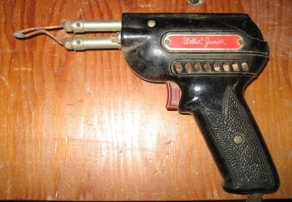
With the highest level of respect, you solderheads need to realize that for the majority of us peons, myself certainly included, this stuff is Greek to us. I really wish I understood this stuff…I think the wave box is pretty cool. I saw the demo at the November meeting…good stuff. I’ve enjoyed this thread, and my 1960’s soldering iron, that looks like a gun, is ready (and it has lights so I could use it in the dark):

SolderingIron.jpg
 

Phyl

Officer Emeritus
Officer Emeritus
Well we tried it and we get just about a 3/4" wave out of the 7095 with our 3 tunzes (of course that's three, not one). I think the wave might be better with the wave box, but I'm not sure. We may build one for the fun of it.

Another thing I learned was that we have 2 of the smaller transformers and one of the larger ones. I'd like to swap out the smaller ones for the larger one. Big difference.
 
redfishbluefish said:
stcreef said:
For anyone that doesn't understand the electronics end of this but would like too, here is a good example and explanation of this exact circuit:

LMAO….ooh like this is going to make it crystal clear! With this knowledge, I'll start building my own computer tomorrow. I did learn a new word.as table. Now with my limited mentality, I'm trying to think of a Jeff Foxworthy definition of as table.

With the highest level of respect, you solderheads need to realize that for the majority of us peons, myself certainly included, this stuff is Greek to us.

I agree with the above, but with this latest drawing I can see the light at the end of the tunnel. The previous drawing had a lot of lines crossing each other and some interesections had a block and some did not. Also, there was an asterisk on some lines. Both of these really threw me off. I think with a little more Q&A I could do this. I see the three out five wire pin connections coming in from the right side and the connection to the LED and the switch (along with the three resistors and two capacitors). The two main questions I have now are the line 1 off the 556 connects between the resistor1 and resistor2. What does the arrow to resistor 2 mean? Secondly, I see the connection to the LED and the on/off switch, but what is connecting to the speed dial or is this part of the 556 itself?

Take a little time to really look at this latest drawing, match it to the components, and it might start to make sense for you too.
 
Phyl said:
And I had to chuckle at you making that diagram "easier to understand"! LOL!

Seems silly, right? But if you look at the first circuit, the "roadmap" is wrong. Just as a roadmap has north always to the top, a simple circuit should always have positive + at the top. In Physics 301, it cannot be stressed enough that your success in understanding and implementing the circuits will depend to a large extent on the development of good systematic procedures. BLA BLA BLA Those basic procedures are that the top line is for positive supply voltages, the bottom of the lines are for negative voltages and GROUND, and the input to the circuit progression goes from left to right. It is the law of a simple schematic. Just like placement of north south east west is the law of a road map.
 
Schematics are a dying art. Typically there are generalized rules. But the biggest is just being as clear and progressive as possible. You can have ten people draw the same circuit and get ten different schematics. And even those probably went through dozens of revisions first. Usually individual companies will have their own standards.

Just like in programming, the easiest way to start is to create flow charts and block diagrams the break the circuit up as needed. But that first diagram I literally threw together in about 5 minutes so I could get out the door as Olivier needed it for another purpose. I should have emailed it to him.

The problem I had with the first schematic was the program had premade components but the pinouts weren't in ideal locations. So I used what I had at the time. The second one if you noticed I had to modify the pinout locations. This wasn't done in a simple graphics program. It is an actual schematic editor so we can create printed circuit boards from the actual drawing. You just see the drawing. In the program, all the dimensions and values of each of the components are taken into consideration.

Any ways, to your questions. If there is a dot/asterisk, that is a connection. If there is an intersection of two lines but no dot/asterisk, it is not connected but a jump. The dots in the middle of the line in the first drawing was a failure of mine to clean the image before posting. Again I was under a time constraint. Sorry.

The resistor with the arrow is an adjustable resistor or better known as a potentiometer. This is the dial you will use to change the wave timing. A potentiometer is a resistor with a wiper. So there are three connections. The two ends and the wiper. In the way we are using this pot, we could get away with only one end of the resistor and the wiper. But it is good practice in this situation to connect the one end to the wiper in case the wiper lifts from the winding. This will prevent an open circuit condition should a mechanical failure occurs in the pot.

Another question I was asked in person about this circuit is why the switch isnt in series with the power. Which is actually a good question. Test time!!! Does anyone know why? There is a very important reason why. Hint: the circuit is to be used for a wavebox. What don't we want to happen?
 

Phyl

Officer Emeritus
Officer Emeritus
We don't want it to get stuck on... but that can't be the answer (I came up with it, lol).
 
stcreef said:
Test time!!! Does anyone know why? There is a very important reason why. Hint: the circuit is to be used for a wavebox. What don't we want to happen?
Let me guess...
Because this leg of the circuit is composed of a power switch bridge and a dynamic-static voltage-sharing absorption circuit (DRwC) bridge, said power switch bridge is composed of a plurality of power switches in series, said dynamic-static voltage-sharing absorption circuit bridge is composed of a plurality of dynamic-static voltage-sharing absorption circuits in series the number of which corresponds to the number of power switches, the positive and negative terminals of each dynamic-static voltage-sharing absorption circuit are connected to the positive and negative terminals of a corresponding power switch, said dynamic-static voltage-sharing absorption circuit consists of a diode D, a capacitance C and a voltage regulator Rw, wherein the diode D is connected in series with the voltage regulator Rw and the capacitance C which are in parallel. So, bla bla bla, it is all because of the dinglehopper effect.
 

redfishbluefish

Officer Emeritus
Officer Emeritus
reneeRN said:
stcreef said:
Test time!!! Does anyone know why? There is a very important reason why. Hint: the circuit is to be used for a wavebox. What don't we want to happen?
Let me guess...
Because this leg of the circuit is composed of a power switch bridge and a dynamic-static voltage-sharing absorption circuit (DRwC) bridge, said power switch bridge is composed of a plurality of power switches in series, said dynamic-static voltage-sharing absorption circuit bridge is composed of a plurality of dynamic-static voltage-sharing absorption circuits in series the number of which corresponds to the number of power switches, the positive and negative terminals of each dynamic-static voltage-sharing absorption circuit are connected to the positive and negative terminals of a corresponding power switch, said dynamic-static voltage-sharing absorption circuit consists of a diode D, a capacitance C and a voltage regulator Rw, wherein the diode D is connected in series with the voltage regulator Rw and the capacitance C which are in parallel. So, bla bla bla, it is all because of the dinglehopper effect.


Hey, that's what I was going to say. LMAO ;D ;D ;D
 

Phyl

Officer Emeritus
Officer Emeritus
That was my other answer. Except I was just going to say "The Dinglehopper Effect".
 
I am sitting here laughing my arse off. If renee switched to the antithesis of everything she posted, it would be pretty darn close to the description of the circuit. Too funny.

Actual Phyllis, your pretty close to the reason. The pump runs continuously without the controller plugged in. So if we just switched the power off to the controller, the pump would run continuously and the wavebox could run dry. So by applying Vcc via the switch to the trigger, the output goes to ground and turns the pump off.
 

malulu

NJRC Member
and for people like Peter (fisheye).

- he run the 6100 pump in his 4 foot tank
- he is NOT using a wave box
- it have some crazy wave going on in that tank right now

If he ever wanted to switch the bump as normal mode. He will be looking for a ON switch.
;)

or, in your case, MUST unplug the cable.
;D
 
stcreef said:
The resistor with the arrow is an adjustable resistor or better known as a potentiometer. This is the dial you will use to change the wave timing. A potentiometer is a resistor with a wiper. So there are three connections. The two ends and the wiper. In the way we are using this pot, we could get away with only one end of the resistor and the wiper. But it is good practice in this situation to connect the one end to the wiper in case the wiper lifts from the winding. This will prevent an open circuit condition should a mechanical failure occurs in the pot.

OK, This explain the missing connection to the speed dial. I'm still just trying to bull through this with pure logic. I have one more question not related to the circuit. I have not used one of these Tunze pumps so it is probably a stupid question: I presume you are unplugging something from the Tunze box with the 5 pin outlet. Now we are plugging our home made wavemaker in instead. What happens to what was originally plugged in? Or is it just not used anymore because it was a controller that was replaced with a better controller?
 
Bruce K said:
OK, This explain the missing connection to the speed dial. I'm still just trying to bull through this with pure logic. I have one more question not related to the circuit. I have not used one of these Tunze pumps so it is probably a stupid question: I presume you are unplugging something from the Tunze box with the 5 pin outlet. Now we are plugging our home made wavemaker in instead. What happens to what was originally plugged in? Or is it just not used anymore because it was a controller that was replaced with a better controller?

The controllable Tunze pumps do NOT come with a controller. You have to buy them separately. The driver box that comes with the pump has a 5 pin socket in it to connect the controller. This circuit will plug in there.
 
You will need a 7094/7095 (don't think the 7096 came out yet) controller box. They're about $280 new. Think I saw one on ebay for about $170.
 
calaxa said:
You will need a 7094/7095 (don't think the 7096 came out yet) controller box. They're about $280 new. Think I saw one on ebay for about $170.

You dont need to buy these controllers if you plan on using this circuit discussed in this thread.
 
stcreef said:
In the never ending quest of perfection, since I threw the above schematic together in a moments notice, I have cleaned up the schematic to make it easier to understand.

1505_14_12_08_10_24_10.jpg


Here is the parts list:

D1 1ea. Red or Blue LED 276-307 $1.99 or 276-311 $3.49
SW1 1ea. SPDT Switches 275-612 $2.99
U1 1ea. LM556 Timer IC 14 pin 276-1728 $1.99
R1 1ea. 10k Ohm Resistor 271-006 5pk $0.99
R2 1ea. 1meg Ohm pots 271-211 $2.99
R3 1ea. 47k Ohm Resistor 271-1342 5pk $0.99
R4 1ea. 470 Ohm Resistor 271-009 5pk $0.99
C1 1ea. .01UF 400V 10% Metal Film Capacitor 272-1051 $1.49
C2 1ea. 10 uF 16V Dipped Tantalum Capacitor 272-1436 $1.59
1ea. 14 pin IC socket 276-1999 $1.29
1ea. perf board 276-148 $1.99
1ea. box 270-1802 $2.69
1ea. knobs 274-403 2ea. $1.99
1ea. 5 din midi cable 42-2151 $7.99
Total $33.46

It's been a while since I etched a PC board. Is it possible to show this sketch in terms of a PC board with the locations of the phyhsical components rather than the schematic symbols and the routing of the interconnecting wires?
 

malulu

NJRC Member
Mike,

My orignal posting on page 1, not simple enough?

Please hang on, after the holiday season, we will get a group project to do this all together...
Tom find a place to get a pre-made pc-board in a fair good price, all you need is stick the parts in, and solder on the back.
;)
 
Top