malulu
NJRC Member
Some Background Info (can be found here http://www.njreefers.org/joomla/index.php?option=com_smf&Itemid=26&topic=12826.0)
My friend (Renee) got the original ReefCentral's posting circuit working (can be found here http://reefcentral.com/forums/showthread.php?s=&threadid=1411393)
But, i am still wondering WHAT IF the ON/OFF was separated by 2 individual controls? would it get better wave?
So, I asked one of my best friend (Johnson Tseng) to help to design a circuit with 2 individual knobs, with some extra features ofcourse...
;D
The Test:
Home - 210 gals - 6 feet tank - 3/4" wave
http://s173.photobucket.com/albums/w61/the_malulu/?action=view¤t=MVI_3881.flv
Red Sand - 9 feet tank - 1" wave
http://s173.photobucket.com/albums/w61/the_malulu/?action=view¤t=MVI_3884.flv
here is the circuit:

But, the result didn't help... to generate the best wave - it seems both controls would have to have the same ON and OFF timing.
Therefore, we added a 3rd switch (SW-#3) to toggle the circuit as 1 control, or a 2 controls mode.
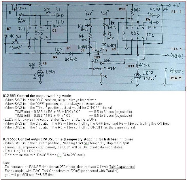
here is the latest circuit:

this image was copied from ReefCentral posting.

the wave-box was made by Renee. thx again!!

Compared to the posting in ReefCentral, this circuit had these additional features:
- a 3-way switch for: ON, OFF, and Timer mode.
- timing would be adjustable between 0.5 to 5 secs (by pushing the #3 switch, the ON/OFF can be adjust with either 1 knob, or 2 separate knobs).
- a push button (as PAUSE) for fish feeding time, it can be adjusted for timing... (~0.5 min to ~4 mins)
- LED-1 to show on/off status
- LED-2 to show it is in pause mode (so we won't mistakenly think it was off if only have one LED)
The circuit seems complicated, BUT, no worry... you can simply follow below TWO maps to get the circuit done quickly.
FONT:

BACK:

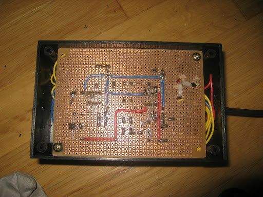
Please Note: the below image looks a little bit different compared to the above mappings,
this is due to i already made the final product BEFORE adding the 3rd switch,
I also made some mess on the below layout, not as clean.
:-[
BOTTOM line is: just use the above TWO MAPPINGS, you WILL be FINE!

some of you may be confused how to read and identify the Capacitor, LED, Diode symbol - here is the illustration compared to the symbol.

here is how you should connect the POTs

here is how you should connect the Switch #2

the front

the back

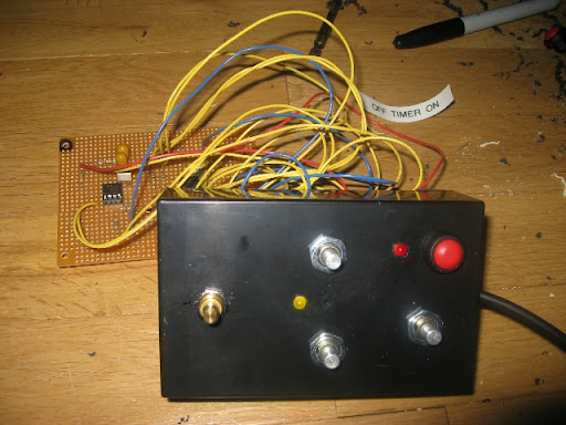
the full front

the full back

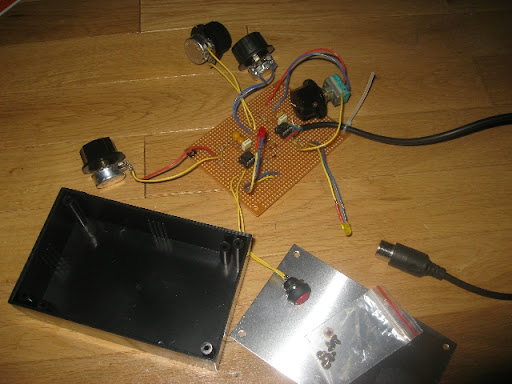
getting ready

the box

the process


it is in

the final product

enjoy!!

oh, it works!
;D
Please let me know if you need more info.
-David
My friend (Renee) got the original ReefCentral's posting circuit working (can be found here http://reefcentral.com/forums/showthread.php?s=&threadid=1411393)
But, i am still wondering WHAT IF the ON/OFF was separated by 2 individual controls? would it get better wave?
So, I asked one of my best friend (Johnson Tseng) to help to design a circuit with 2 individual knobs, with some extra features ofcourse...
;D
The Test:
Home - 210 gals - 6 feet tank - 3/4" wave
http://s173.photobucket.com/albums/w61/the_malulu/?action=view¤t=MVI_3881.flv
Red Sand - 9 feet tank - 1" wave
http://s173.photobucket.com/albums/w61/the_malulu/?action=view¤t=MVI_3884.flv
here is the circuit:

But, the result didn't help... to generate the best wave - it seems both controls would have to have the same ON and OFF timing.
Therefore, we added a 3rd switch (SW-#3) to toggle the circuit as 1 control, or a 2 controls mode.
here is the latest circuit:
this image was copied from ReefCentral posting.

the wave-box was made by Renee. thx again!!
Compared to the posting in ReefCentral, this circuit had these additional features:
- a 3-way switch for: ON, OFF, and Timer mode.
- timing would be adjustable between 0.5 to 5 secs (by pushing the #3 switch, the ON/OFF can be adjust with either 1 knob, or 2 separate knobs).
- a push button (as PAUSE) for fish feeding time, it can be adjusted for timing... (~0.5 min to ~4 mins)
- LED-1 to show on/off status
- LED-2 to show it is in pause mode (so we won't mistakenly think it was off if only have one LED)
The circuit seems complicated, BUT, no worry... you can simply follow below TWO maps to get the circuit done quickly.
FONT:

BACK:

Please Note: the below image looks a little bit different compared to the above mappings,
this is due to i already made the final product BEFORE adding the 3rd switch,
I also made some mess on the below layout, not as clean.
:-[
BOTTOM line is: just use the above TWO MAPPINGS, you WILL be FINE!
some of you may be confused how to read and identify the Capacitor, LED, Diode symbol - here is the illustration compared to the symbol.

here is how you should connect the POTs

here is how you should connect the Switch #2

the front

the back

the full front

the full back

getting ready

the box

the process


it is in

the final product

enjoy!!
oh, it works!
;D
Please let me know if you need more info.
-David


